![[TNO-logo]](banner.gif)

Computer history TNO-FEL:
CDC CYBER 180-840A
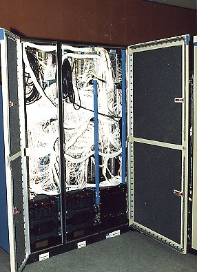
Control Data CYBER 180-840A
Central Processor
As part of the CYBER 180 family, this (at that time) high-performance system used
a combination of subnanosecond emitter-coupled logic (ECL) circuits
and large scale integration (LSI) arrays to provide high reliability compact packaging,
low power requirements, and high computation speeds.
The Model 840 had a micro-coded single central processor that included
cache memory and was capable of supporting up to l6M 64-bitwords of main memory (134 Mbytes).
The central processor was a high-speed arithmetic unit, communicating only with central memory. It operated
independently from the peripheral processors,
which did all input/output, and is free to carry on computation unencumbered
by the input/output requirements.
Instruction and program address pipelines held instructions and addresses during execution,
allowing several instructions to be in different stages of execution simultaneously.
Central Memory
The Model 840 central memory was composed of eight logically independent banks
that are composed of 256K metallic-oxide semiconductor (MOS) chips. The MOS chips provided
a complete read/write cycle time for one bank of 384 nanoseconds (major cycle). The banks were
phased so that successive addresses are in different banks to permit operation of central memory at
much higher rates than the basic bank cycle time.
Three central memory interface ports are provided by the Model 840:
- Central processor/port
- Input/output unit/port
- External port for Control Data MAP or CYBERPLUS processors
A data distributor provided service to each of the memory
interface ports on a priority basis and distributed data between
the ports and the memory. The data distributor also contained the
Error Correction Code (ECC) generators and the Single Error
Correction/Double-Error Detection (SECDED) logic.
When a word was read from memory, any single-bit-errors were corrected.
Multiple-bit errors were detected and reported to the system via the maintenance
access channel and the maintenance control unit.
Input/Output Unit
The input/output unit (IOU) consisted
of 10 peripheral processors (PP) and 12 data channels that operated independently and
simultaneously as stored-program computers. Options could be selected
to expand to 15 or 20 peripheral processors overall, plus adding an additional 12 data channels.
Each channel could transfer data into or out of the system at a
maximum rate of 250 nanoseconds per 12-bit word.
All channels were bidirectional, transferring 12 bits (plus parity),
and each could be connected to one or more external devices. Channels could
be operated simultaneously.
The IOU also contained a maintenance control unit (MCU) that was a selected
peripheral processor programmed to initialize the system. It monitored
the operation of the system, performed system integrity verification through diagnostics,
detected system faults, and took corrective action.
The system included a reserved communications line interface for use
in providing remote technical assistance (RTA). Remote maintenance or RTA could
be performed by technical specialists dialing into this special interface.
Dual State
The Model 840 was capable of dual state operation, where the central processor
executes two different instruction sets. The first set, called the 170 state,
executed the instruction set required by the NOS or NOS/BE operating system, its products,
utilities, and applications. The 170 state
supported real memory addressing,
uses 60-bit words (6-bit characters) and a 12-bit mode for the
peripheral processors.
The second set, called the 180 state,
executed the instruction set required
by the NOS/VE
operating system, its products, utilities and applications.
The 180 state supports virtual memory addressing, used
64-bit words (8-bit bytes) and a 16-bit mode
for the peripheral processors.
The central processor could change states dynamically, running
both the NOS(/BE) and NOS/VE operating systems simultaneously.
Central memory was divided between the two states at system initialization time.
The IOU (input-output unit) was also divided at system initialization time so that
peripheral processors
were assigned to a state.
For the 170 state, the peripheral processors used a 12-bit word mode;
in the 180 state, the peripheral processors
use a 16-bit word mode.
 [email protected]
25/02/1998
