
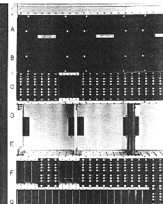
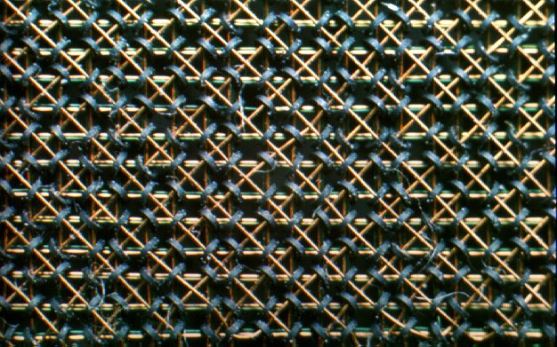
CDC 6000 series and CYBER 70-series core memory.
One of the 12 layers of a memory block showing 64*64 bits.
Enlarge to real size or look at macro photo of some bits.
![[TNO-logo]](banner.gif)
 The 6000 series CPU was a Reduced Instruction Set Computer (RISC)
long before it was popular to have
a reduced instruction set. The CPU was usually said to have around 74
CPU instructions
(the exact number depends on how you count them), but by modern standards
the number was less than the number one counts as "RISC".
The rough number 74 counts each of 8 addressing
modes three times, whereas you could reasonably say that an addressing
mode shouldn't be counted as a separate instruction at all. Despite the
lean instruction set, there were few complaints about the instruction set
missing instructions.
The 6000 series CPU was a Reduced Instruction Set Computer (RISC)
long before it was popular to have
a reduced instruction set. The CPU was usually said to have around 74
CPU instructions
(the exact number depends on how you count them), but by modern standards
the number was less than the number one counts as "RISC".
The rough number 74 counts each of 8 addressing
modes three times, whereas you could reasonably say that an addressing
mode shouldn't be counted as a separate instruction at all. Despite the
lean instruction set, there were few complaints about the instruction set
missing instructions.
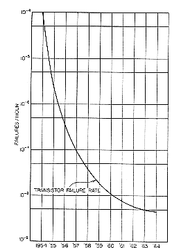
The system was designed around packages of discrete components and transistors.
They were regarded as becoming "reliable" (see transistor
reliability graph from [Thornton70]).
As the CDC 6600 required 400,000 transistors, it was estimated
that the MTBF of the system (based upon transistor reliability) would be
over 2000 hours. The technique used was that of Direct Coupled Transistor Logic (DCLT).
 Central memory (CM) was organized as 60-bit words. In early days (6000-series)
the memory had no parity and was build up from
core memory
blocks (6.75 by 6.75 by 3.625 inches tall), each containing 4096 lines of
12 bits.
Five blocks in a row comprised central memory. One block
occupied the memory of a single
Peripheral Processor or PP.
Central memory (CM) was organized as 60-bit words. In early days (6000-series)
the memory had no parity and was build up from
core memory
blocks (6.75 by 6.75 by 3.625 inches tall), each containing 4096 lines of
12 bits.
Five blocks in a row comprised central memory. One block
occupied the memory of a single
Peripheral Processor or PP. Click for more information on how core memory works.
There was no byte
addressability. If you wanted to store multiple characters in a 60-bit
word, you had to shift and mask. Typically, a six-bit character set was
used, which meant no lower-case letters. These systems were meant to be
(super)computing engines, not text processors!
To signal the end of a text string,
two different coding techniques were invented. One, the so-called 64 character set
was CDC-standard. A line end comprised two null-"bytes" at the end of a word followed
by a full zero word. The 63 character set, quite popular in the Netherlands and
the University of Austin, signalled the line termination by two
null-"bytes" at the end of a word.
Michigan State University (MSU) invented a 12-bit character
set, which was basically 7-bit ASCII with 5 wasted bits per character.
Other sites used
special shift/unshift characters in a 6-bit character set to achieve upper/lower
case.
CDC 6000 series and CYBER 70-series core memory.
One of the 12 layers of a memory block showing 64*64 bits.
Enlarge to real size or
look at macro photo of some bits.
Some systems of the short-lived Cyber 70 Series, which followed the 6000 Series, added a Compare and Move Unit (CMU) which did complex character handling in hardware. The CMU was not used much, probably due to compatibility concerns. The CMU was such a departure from the 6000's lean and mean instruction set that the CDC engineers must have been relieved to be able to omit it from the next line of computers, the Cyber 170 Series.
Central Memory (CM) addresses were 18 bits wide in later series, but in the original 6000 line, the sign bit had to be zero, limiting addresses to a range of 17 bits. Even without the sign bit problem, though, the amount of addressable central memory was extremely limited by modern standards. A maxed-out 170 Series from around 1980 was limited to 256K words, which in total bits is slightly less than 2 megabytes (using 8-bit bytes purely as a means to compare with modern machines). In the early days, 256K words was more than anyone could afford, but eventually this addressability problem became a real problem in the NOS and NOS/BE "fixed memory" operating systems.
A workaround was the Extended Core Storage
(ECS) unit. This was auxilliary memory made from the same magnetic cores
of which CM was fabricated. (More recent versions of ECS were named ESM,
Extended Semiconductor Memory.) ECS was accessible only by block moves
to or from CM. The initial ECS had a read and store cycle time of 3.2 microseconds;
480 bits (8 word block) storage "words"; 125,000 CM words bank capacity;
up to 16 banks; CM to/from ECS rate: 10 central memory (60 bit) words per microsecond.
ECS could be shared by 4 CYBER systems. Operating systems used this to share
the job load, exchange information and so on.
The address width of ECS was 24 bits.
But not being able to run programs or directly access
data from ECS meant it was used mostly to store operating system tables
or to swap programs. In the 180 series of systems, one could emulate ECS
in the upper part of memory (above 256 KWords)
"Swap" programs because there was no virtual memory (hardware) on the machine. Memory management was primitive (but effective). Each user program had to be allocated a single region of continguous memory. This region started at the address in the RA (Reference Address) register and went for a certain number of words, as dictated by the contents of the FL (Field Length) register. The CPU hardware always added the contents of the RA register to all address references before the memory access was made; as far as the program was concerned, its first address was always 0. Any attempt to access memory >= FL resulted in a fatal error.
As programs came and went from CM, holes opened up between regions of
memory. To place programs optimally in memory, an operating system had
to suspend the execution of a program, copy its field length to close up
a gap, adjust the RA register to point to the program's new location, and
resume execution.
On some systems that had ECS, it was actually faster to do a block move
to ECS and then a block move from ECS than it was to move memory in a tight
loop coded with the obvious load and store instructions.
Incidentally, the CPU enforced access to ECS in much the same way as
it did to CM. There were two registers specifying the beginning address
and number of words of the single region of ECS to which the CPU had access
at any time. Depending on system parameters,
user programs could be forced to have an ECS field length
of zero.
The 6000 CPU had a load/store architecture: data in memory could be referenced only by load and store instructions. To increment a memory location, then, you had to execute at least three instructions: load from memory, do an add, and store from memory.
Memory access on 6000 series systems was interleaved into 8 independent banks or core memory, so usually the CPU did not have to wait for a memory cycle to complete before starting a new one.
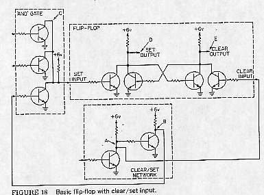
The designs of one of the basic CDC 6000 series circuits[Thornton70]
A0 was a pretty worthless register. By convention, code generated by FORTRAN kept a pointer to the beginning of the current subroutine in A0, to aid in subroutine traceback in cause an error occurred. Similarly, X0 was not too useful, as it could neither be loaded from or stored to memory directly. However, it was moderately useful for holding intermediate results.
Many programmers felt that CDC should also have hardwired B1 to 1, since there was no CPU register increment or decrement instruction. Since there was no register hardwired to 1, many assembly language programs started with "SB1 1", the instruction to load a 1 into B1.
There was no condition code register in the 6000 Series. Instructions that did conditional branches actually did the test and then branched on the result. This, of course, is in contrast to many architectures such as the Intel x86, which uses a condition code register that stores the result of the last arithmetic operation.
Mark Riordan: "When I learned about condition code registers years after first learning the 6000 architecture, I was shocked. Having a single condition code register seemed to me to be a significant potential bottleneck. It would make execution of multiple instructions simultaneously very difficult. I still think that having a single condition code register is stupid, but I must admit that the Intel Pentium Pro, for instance, is pretty darned fast anyway."
The instruction set included integer (I), logical (B), and floating-point
(F) instructions. The assembler syntax was different than most assemblers.
There were very few different mnemonics; differentiation amongst instructions
was done largely by operators. Arithmetic instructions were mostly three-address;
that is, an operation was performed on two registers, with the result going
to a third register. (Remember that the 6000's load/store architecture
precluded working with memory-based operands.) For instance, to add two
integers in X1 and X5 and place the result in X6, you did:
IX6 X1+X2
A floating-point multiplication of X3 and X7, with the result going
to X0, would be:
FX0 X3*X7
An Exclusive Or of X6 and X1, with the result going to X6, would be:
BX6 X6-X1
Initially, there was no integer multiply instruction. Integer multiply was added to the instruction set pretty early in the game, though, when CDC engineers figured out a way of using existing floating-point hardware to implement the integer multiply. The downside of this clever move was that the integer multiply could multiply only numbers that could fit into the 48-bit mantissa field of a 60-bit register. If your integers were bigger than 48 bits, you'd get unexpected results.
You'd think that 60-bit floating-point numbers (1 sign bit, 11-bit exponent including bias, 48-bit bit-normalized mantissa) would be large enough to satisfy anyone. Nope: the 6000 instruction set, lean as it was, did include double precision instructions for addition, subtraction, and multiplication. They operated on 60-bit quantities, just as single precision numbers; the only difference is that the double precision instructions returned a floating point number with the 48 least-significant bits, rather than the 48 most-significant bits. So, double precision operations--especially multiplication and division--required several instructions to produce the final 120-bit result. Double precision numbers were just two single precision numbers back-to-back, with the second exponent being essentially redundant. It was a waste of 12 bits, but you still got 96 bits of precision.
You can tell that floating point was important to Control Data when you consider
that there was separate rounding versions of the single precision operations.
These were rarely used, for some reason. The non-rounding versions needed
to be in the instruction set because they were required for double-precision
work. The mnemonic for double precision operations was D (as in DX7
X2*X3) and for rounded operations was R.
Some 170-series systems CPU's rounded in a funny way: 1/3 rather than 1/2
of the least significant bit.
Another instruction that is surprising to find in such a lean instruction set was Population Count. This instruction counted the number of 1 bits in a word. CX6 X2, for instance, would count the number of bits in X2 and place the result in X6. This was the slowest instruction on most 6000 machines. Rumor had it that the instruction was implemented at the request of the National Security Agency for use in cryptanalysis.
 The 6000 series systems and their successors had functional units. Some
models (e.g. 6600 and Cyber 74)
even had two multiply units. This allowed multiple operations
to take place simultaneously when the A, B and X-registers were scheduled optimally.
Whether a operation (or even the next one)
could be scheduled to a functional unit or the CPU really had to hold
until results being calculated could be used was determined by the
hardware "score board" located in the "stunt box".
There appeared several analysis articles
that based upon Petri-nets (some references at the bottom)
made optimal use of the parallelism available
in the CPU. Conflicts of several "types" could occur.
The 6000 series systems and their successors had functional units. Some
models (e.g. 6600 and Cyber 74)
even had two multiply units. This allowed multiple operations
to take place simultaneously when the A, B and X-registers were scheduled optimally.
Whether a operation (or even the next one)
could be scheduled to a functional unit or the CPU really had to hold
until results being calculated could be used was determined by the
hardware "score board" located in the "stunt box".
There appeared several analysis articles
that based upon Petri-nets (some references at the bottom)
made optimal use of the parallelism available
in the CPU. Conflicts of several "types" could occur.
The 6600/CYBER 74 functional units were: Branch unit
(instruction groups 00-07), Boolean unit (10-17),
Shift unit (20-27, 43), FP addition (30-35), Long addition (36-37),
FP multiply (40-42), FP divide (44, 45,47), Incerement (50-77).
The model 76 types organized this a little different: Boolean unit (10-17, 25, 27),
Shift unit (20-27, 43), Normalize (24, 25),FP add (30-35), Long add (36-37),
FP multiply (40-42), FP divide (44, 45), Population count (47), Incerement (50-77).
![]()
![]()
(with special thanks to Mark Riordan who provided the initial basis for this page)
 [email protected]
